
How Should a Brush Cutter Manufacturer Control a 1500mm Shaft?
See how a brush cutter manufacturer should control a 1500mm shaft assembly, from tube straightness and drive engagement to gearbox alignment and batch checks.
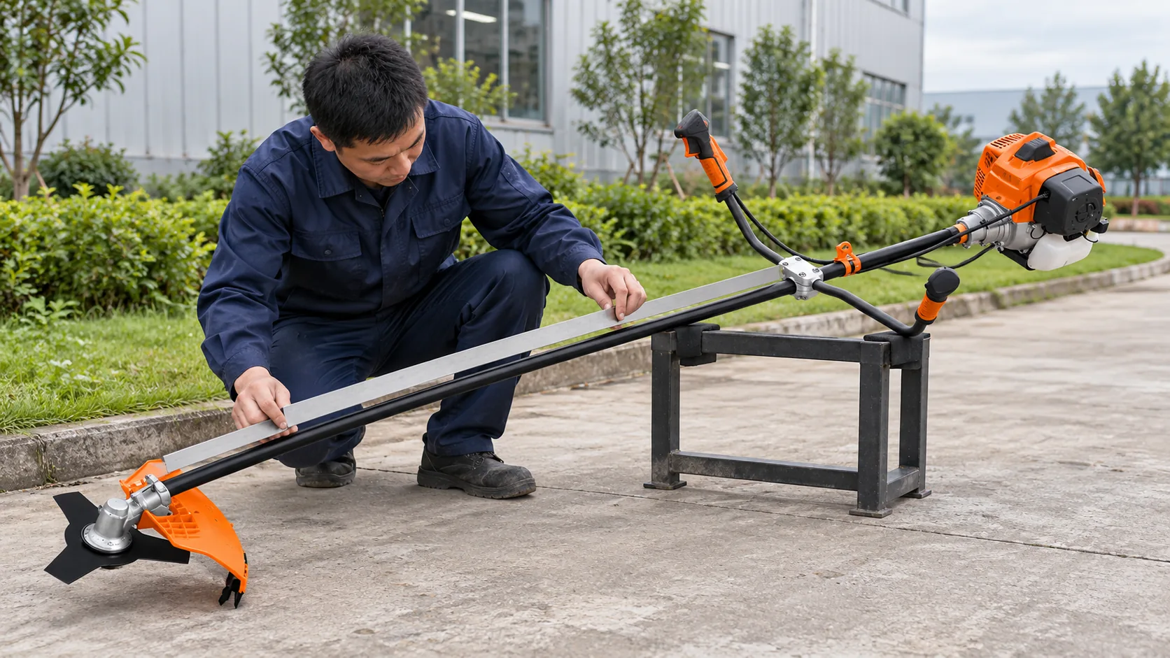
How Should a Brush Cutter Manufacturer Control a 1500mm Shaft Assembly?
A brush cutter manufacturer cannot judge a long shaft assembly by its outer dimensions alone. Tube straightness, internal drive engagement, engine-side seating, gearbox installation and handle position all affect the finished machine.
For an importer approving a 52cc sample, the production question is whether those relationships can be repeated across the bulk order. A shaft that measures correctly may still be assembled differently from the approved machine.
Quick answer: Control the 1500 mm shaft as a complete drive assembly:
- Check tube straightness, diameter and working length before final assembly.
- Confirm internal drive engagement, engine-side seating and gearbox position on the assembled machine.
- Compare handle placement, cable routing and running behavior with the approved sample across selected production units.
Record the confirmed assembly in the order specification so replacement parts and repeat orders can be matched to it.
A 1500 mm measurement does not prove the drive system fits
A straight-shaft brush cutter transfers power from the engine-side connection through an internal drive shaft to the gearbox. The outer tube supports that drive system and provides mounting space for the handle and related components.
The tube may measure 1500 mm yet still be bent, paired with an unsuitable internal shaft or fitted to a gearbox that has not seated correctly. Inspect the physical dimensions and the completed transmission path as separate production checks.
Use the TM-CG520TJ configuration as the production reference
The TM-CG520TJ brush cutter is listed with a 1E44F-5J two-stroke air-cooled engine, 51.7cc displacement and rated output of 1.80 kW at 6500 rpm. Its working shaft is listed as 1500 mm long and 28 mm in diameter. The reference configuration also specifies a 3000 ±200 rpm idle speed, diaphragm carburetor, 1:30 mixed-fuel ratio and 1200 ml fuel tank.
These figures identify the model being discussed; they do not establish that every part of an assembled unit fits correctly. The final quotation or proforma invoice should identify the configuration to be compared with the approved sample.
| Production point | What to observe | Why a dimension alone is insufficient |
| Outer tube | 28 mm diameter, 1500 mm working length and visible straightness | A tube can have the correct dimensions but be deformed. |
| Internal drive | Normal seating and rotation at both ends | External measurements do not show engagement. |
| Gearbox and handle | Position and orientation against the approved sample | Correct parts can still be installed inconsistently. |
Inspect tube straightness before the cutting end is fitted
Look for visible bending or handling damage before the gearbox and cutting attachment turn the shaft into a finished unit. The factory’s measurement method may vary, but a tube suspected of deformation should be checked before assembly continues.
A distorted tube may still accept a gearbox and turn during a brief low-speed check. Problems can become more apparent as rotational speed rises or the machine works under cutting load. Ask how long tubes are stored, moved and inspected on the production line.
Check engagement from the engine connection to the gearbox
The internal drive shaft needs to seat at both ends without forcing the gearbox into place or leaving it short of its intended position. After assembly, check for obvious binding when the drive system is turned according to the factory’s inspection procedure.
The TM-CG520TJ’s 1E44F-5J engine and 1500 mm shaft belong to one specified machine configuration. If unusual vibration is concentrated near their connection, inspect mounting alignment, clutch-side engagement and shaft seating before changing engine settings.
At the cutting end, compare gearbox seating and orientation with the approved sample. Its fit depends on the selected gearbox and internal drive connection as well as the 28 mm outer tube. The guard and cutting attachment should also sit in their intended positions.
Repeat handle placement and control routing
Mark or otherwise document the approved handle location and orientation. Machines with identical engines and shafts can feel different if operators must hold their handles in noticeably different positions.
Follow the throttle cable and switch wiring from the power unit to the handle. The routing should not pull tight at the approved handle position or leave loose sections where they interfere with normal operation. Check this on more than one finished unit; visual estimation during assembly can produce variation.
Investigate vibration in stages
Correct visible assembly faults before a running check. High-speed operation cannot make a bent tube, loose gearbox or incorrectly installed cutting attachment acceptable.
Once assembled correctly, observe mechanical noise, engagement and vibration during controlled operation. The listed idle reference for the TM-CG520TJ is 3000 ±200 rpm; compare running behavior with the confirmed configuration and approved sample. If severe vibration develops, stop the engine and wait for all movement to cease before inspecting the machine.
Start with the cutting attachment: a bent, poorly centered or incorrectly fitted blade can cause vibration. If the symptom remains with a known-correct attachment, work backward through the gearbox, internal drive shaft, tube, engine-side connection and mounting points.
TM-CG520TJ: a defined assembly to compare
This model is relevant when evaluating how a brush cutter manufacturer controls a 1500mm shaft assembly. Its listed 28 mm tube and 1500 mm working length provide measurable starting points, while the engine-side connection, internal drive, gearbox and handle must be checked on the actual approved machine.
| Review the TM-CG520TJ |
Compare production units with the approved sample
One approved sample establishes a reference, not a result for every machine in the order. Select finished units from production and compare their assembly details with that reference. This check looks for repeatability; it does not require repeating a full performance trial on every unit.
Importer production checklist
- Match machine identification and the 1E44F-5J engine designation to the confirmed order.
- Check the 28 mm shaft diameter and 1500 mm working shaft length.
- Inspect selected tubes for visible bends or handling damage.
- Check internal drive seating at the engine and gearbox ends.
- Compare gearbox seating and orientation with the approved sample.
- Compare handle location and orientation between selected units.
- Check throttle-cable and switch-wire routing.
- Confirm guard and cutting attachment installation before running checks.
- Investigate abnormal vibration or mechanical noise rather than recording only whether the engine starts.
Protect the assembly in packing and repeat orders
The TM-CG520TJ product information lists kraft-carton or customized color-box packaging options. Confirm the internal arrangement for the chosen order: the long tube should not need to be forced into its carton or held under obvious bending pressure from other parts. If packed partly disassembled, dealers need a clear way to identify the intended shaft, gearbox, handle and power-unit connections.
For replacement parts, “28 mm × 1500 mm shaft” is a useful description but does not establish internal drive profile or connection compatibility. Identify the machine model and confirmed assembly first. Document any verified interchangeability across models.
Before a repeat order, reconfirm the engine code, shaft dimensions, internal drive and gearbox configuration, handle arrangement and relevant packing details. Record an accepted component change in the purchasing documents before production begins.
Frequently asked questions
Does a 1500 mm tube confirm that the brush cutter shaft is assembled correctly?
No. Check straightness, internal drive engagement, engine-side seating and gearbox installation on the completed machine.
What can cause vibration on a long-shaft brush cutter?
Possible sources include the cutting attachment, gearbox, internal drive, tube or mounting connections. Inspect the attachment first, then trace any remaining vibration through the assembly.
Is a 28 mm × 1500 mm replacement shaft necessarily compatible with the TM-CG520TJ?
Not necessarily. The internal drive profile and both end connections must match the confirmed machine configuration.
How many machines should be checked in a bulk order?
Set a sampling plan appropriate to the order and inspection agreement. Compare selected finished machines with the approved sample rather than relying on that sample alone.
What should be reconfirmed before a repeat order?
Reconfirm the engine designation, complete shaft assembly, gearbox and handle arrangement, and any approved changes that affect fit or spare-parts identification.
Set the shaft assembly as an order reference
When discussing the TM-CG520TJ with a brush cutter manufacturer, confirm the complete 1500 mm shaft assembly against the approved sample and use it to guide production inspection, spare-parts requests and repeat orders.
| Ask About the Configuration |