
Brush Cutter Won’t Turn Off: Stop Switch and Wiring Checks
Learn why a brush cutter won’t turn off, how to inspect the stop switch and wiring, and what dealers should check before ordering control boxes.
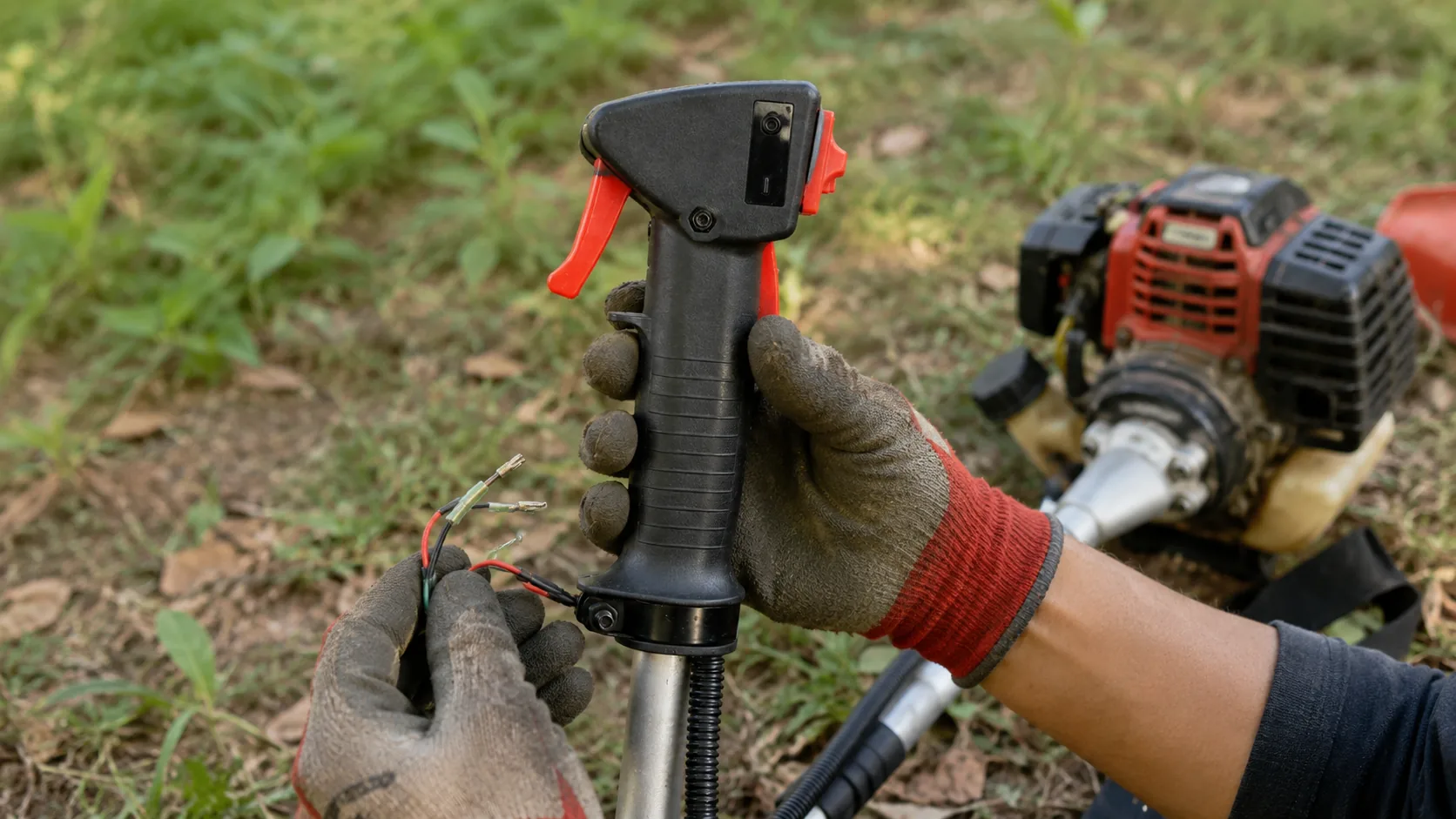
Field Service & Dealer Troubleshooting Guide
A brush cutter that will not turn off may continue cutting normally, but its shutdown system is no longer safe. The most common causes are a faulty stop switch, disconnected wiring, worn switch contacts, poor grounding, or a broken wire between the control handle and ignition system. Dealers and repair shops should treat this as a control-system fault rather than advising customers to keep using the machine.
The inspection should begin with safe engine shutdown, followed by a physical check of the control box, wiring route, terminals, throttle trigger and trigger lockout. For importers purchasing replacement control boxes, appearance alone is not enough. Mounting diameter, cable travel, connectors, wire length and switch-circuit compatibility must all be confirmed before a bulk order.
| Quick answer: | A brush cutter won’t turn off when pressing the stop switch if the switch no longer completes the required ignition shutdown circuit. First release the throttle, keep clear of the cutting attachment and use only the emergency stopping method specified for the actual engine. After the engine has stopped and cooled, disconnect the spark-plug cap. Inspect the switch movement, housing, terminals, ground connection and wiring from the handle to the engine. Importers should test replacement control boxes on an actual machine before bulk purchasing because visually similar parts may use different connectors, cable travel or wiring arrangements. |
1. What the Brush Cutter Stop Switch Actually Controls
On a petrol brush cutter, the stop switch normally shuts down the engine by interrupting or grounding the ignition circuit. The exact circuit arrangement depends on the engine and ignition design, but the practical result is the same: operating the switch must prevent the spark plug from continuing to ignite the fuel mixture.
The control handle may contain several parts that work together but perform different jobs. These can include the stop switch, throttle trigger, trigger lockout, throttle cable connection, return springs, electrical wires and plastic housing. The throttle trigger controls engine speed, while the stop switch controls shutdown. A brush cutter may therefore accelerate and cut normally even though the stop switch circuit has failed.
A damaged control box can also create more than one complaint. Broken internal mounting points, trapped wiring or a displaced spring may affect the shutdown switch, throttle return and lockout at the same time. Repair technicians should test every control function instead of replacing one visible component and assuming the complete handle assembly is safe.
| Stop switch | Stops ignition so the engine can shut down. |
| Throttle trigger | Controls engine speed through the throttle cable. |
| Trigger lockout | Helps prevent accidental throttle operation. |
| Control-box housing | Positions and protects the switch, trigger, wiring and cable connection. |
2. Diagnostic Table for a Brush Cutter That Won’t Turn Off
The timing and behavior of the fault can help narrow the inspection. A stop switch that fails immediately after handle adjustment or transport points toward pinched wiring, loose terminals or connector movement. A failure that develops gradually is more likely to involve worn contacts, corrosion, vibration damage or an internal wire break.
| Symptom | Possible Cause | Inspection Point | Recommended Action |
| Switch moves normally, but engine keeps running | Open circuit, loose terminal or poor ground | Switch terminals, connectors and grounding point | Reconnect, clean or replace damaged components |
| Switch works only at one angle | Worn contacts or broken internal wire | Switch body and wire exit point | Replace the switch or complete control box |
| Fault started after handle adjustment | Stretched, pinched or disconnected wire | Handle bracket, cable ties and shaft routing | Correct routing and repair damaged wiring |
| New control box does not stop engine | Wrong wiring or incompatible replacement | Wire count, terminals, circuit state and connectors | Confirm compatibility and reinstall correctly |
| Stop switch and throttle both feel abnormal | Cracked housing, trapped parts or incorrect assembly | Housing posts, trigger spring, lockout and cable holder | Replace or correctly rebuild the assembly |
3. What to Do Immediately When the Stop Switch Fails
Release the throttle and keep the cutting attachment away from people, animals and nearby objects. Do not touch the spark-plug lead, blade, trimmer head, gearbox or hot engine parts while the machine is running. Place the brush cutter in a stable position only when this can be done without approaching the rotating attachment.
Use the emergency stopping procedure specified in the operating manual for the actual engine. On some petrol brush cutters, moving the choke to the closed position may stall the engine, but this procedure is not identical for every model. Relying on the choke, fuel tap or fuel depletion every time is not an acceptable permanent solution.
Wait until the blade or trimmer head has stopped completely. After the engine has cooled, disconnect the spark-plug cap before opening the control box or checking electrical connections. Do not return the machine to service until the normal stop switch has been repaired and successfully tested.
| Safety priority: A machine that cannot be shut down quickly is unsafe even when the engine, gearbox and cutting attachment appear to operate normally. Stop-switch repair should be completed before further cutting tests or customer use. |
4. Inspecting the Switch Mechanism, Wiring and Ground Circuit
Begin with the exterior of the control box. A cracked housing, displaced switch, loose cover, missing screw, broken mounting post or deformed trigger component may prevent the switch from reaching its intended stop position. With the engine off, operate the switch several times. It should move through its designed range without excessive looseness, sticking or unusual resistance.
Physical Control Check
|
Electrical Route Check
|
Do not spray aggressive solvent into the control box. Strong chemicals may damage plastic parts, wire insulation or internal contact surfaces. If the switch works only when pushed at a particular angle, held with excessive force or operated repeatedly, the internal contacts may already be worn. Replacement is generally more reliable than teaching the customer an unusual operating method.
A wire may be broken internally while its insulation still looks normal. Control wiring is exposed to engine vibration, handle movement, storage pressure, carton packing, assembly work and repeated bending. Areas near the control-box outlet, handlebar bracket, shaft clamps and engine connectors deserve particular attention.
A trained technician can use a multimeter to check whether the stop switch changes circuit state when operated. The expected reading depends on the ignition design, so continuity testing should follow the wiring diagram or service information for the actual brush cutter. Guessing based only on wire color can lead to incorrect connections.
5. Why a Newly Installed Control Box May Still Fail
Installing a new control box does not automatically solve a brush cutter stop-switch problem. The replacement may be wired incorrectly, assembled with trapped components or designed for a different machine. Even when the external housing looks identical, the switch circuit, cable connection and internal dimensions may differ.
- Connecting stop-switch wires to the wrong terminals.
- Leaving a ground wire disconnected.
- Trapping wiring between the two housing halves.
- Routing the throttle cable around the wrong guide point.
- Tightening the housing before springs and triggers are positioned.
- Installing the switch in the wrong direction.
- Using screws that are too long for the plastic mounting posts.
- Fitting the box to an incorrect handlebar or shaft diameter.
- Leaving the throttle trigger partly engaged.
- Failing to test the trigger lockout and stop switch after assembly.
Before starting the engine, confirm that the throttle trigger returns fully when released. The trigger lockout should prevent accidental throttle operation, and the stop switch should move cleanly. The housing must close without crushing wires or forcing internal parts out of position.
After installation, test the machine in a clear area with the cutting attachment safely positioned. Confirm normal starting, throttle response, return to idle, lockout operation and shutdown. A repaired machine should not be returned to the customer after checking only that the engine accelerates.
6. When to Replace the Complete Brush Cutter Control Box
Replacing only the switch may be reasonable when the housing, throttle trigger, lockout, wiring and cable holder remain in good condition. A complete control-box replacement is more practical when several internal parts are damaged or when the original assembly has already been modified by previous repairs.
| Replace the Complete Assembly When | Why Replacement Is More Practical |
| Housing or screw posts are cracked | The switch and trigger may no longer remain correctly aligned. |
| Internal wiring has several damaged sections | Multiple repairs increase the risk of repeat failure. |
| Trigger or lockout does not return correctly | The fault affects both shutdown and throttle safety. |
| Cable holder no longer secures the throttle cable | Incorrect cable position may alter idle and acceleration. |
| Corrosion has affected several contacts | Cleaning one contact may not restore reliable operation. |
| Correct individual switch is unavailable | A matched assembly reduces improvised repair work. |
|
Replacement Spare Part Brush Cutter Control Box 1101A replacement control-box assembly for brush cutter and grass cutter repair, maintenance and wholesale spare-parts supply. Buyers should confirm mounting size, trigger structure, wiring, connectors, cable connection and machine compatibility before ordering. |
|
7. Compatibility Checks for Importers and Spare-Parts Dealers
Brush cutter control boxes often look similar in photographs while differing in important mechanical and electrical details. A small difference in mounting diameter, throttle-cable travel or connector type can make a complete shipment unsuitable for the intended machines.
Before purchasing a replacement, compare the shape of both housing halves, mounting opening, screw positions, stop-switch direction, number of electrical wires, connector shape, terminal type, wire length, throttle-cable end and required cable movement. Buyers should also confirm the trigger and lockout design, right-hand or left-hand mounting position and compatibility with the specific engine and brush cutter model.
Importers should request clear photographs of the original part from several angles. Images should show the external housing, mounting opening, screw layout, cable end, wire colors and connectors. When model information remains uncertain, supplying a physical sample is often the safest way to reduce compatibility mistakes.
| Buying Focus | Common Risk | Dealer Advice |
| Handlebar mounting diameter | Housing cannot close or remain secure | Measure the actual mounting tube before approval |
| Throttle-cable travel | Engine cannot reach full speed or return to idle | Test cable movement on a complete machine |
| Switch wiring arrangement | Engine still will not shut down | Confirm circuit operation rather than wire color alone |
| Connector and terminal type | Technicians must cut and modify new parts | Approve the exact plug and terminal configuration |
| Part identification | Similar versions are mixed in storage | Use separate item codes, labels and carton markings |
8. Importer and Dealer Control-Box Checklist
Control boxes are small spare parts, but a minor dimensional or wiring difference can make an entire shipment difficult to sell. Sample approval should include installation and engine testing rather than visual comparison alone. Dealers carrying several brush cutter models should maintain separate compatibility records for each control-box version.
| Before Ordering | Before Shipment and Resale |
|
|
For repeat orders, compare incoming parts with the previously accepted sample. Technicians should check the housing, wire routing, connector retention, switch movement, throttle-cable connection and shutdown performance. This helps control consistency when suppliers modify molds, terminals or internal components without a major visible change.
Dealers can reduce after-sales complaints by testing the stop switch during pre-delivery inspection and routine servicing. Wiring should not be stretched when handlebars are adjusted. Avoid sharp bends, hot engine surfaces, rotating parts and exposed metal edges. Control-box screws should be secure but not overtightened into plastic posts.
9. Frequently Asked Questions
01. Why does my brush cutter keep running after I press the stop switch?
The switch may no longer be grounding or interrupting the ignition circuit. Common causes include loose terminals, a disconnected ground wire, worn contacts, broken wiring, corrosion or an incompatible replacement control box.
02. Can I continue using a brush cutter that won’t turn off?
No. The machine cannot be shut down quickly if the throttle sticks, the cutting attachment becomes entangled or another unsafe condition occurs. Repair and test the normal shutdown system before further use.
03. Can a broken wire cause the same problem as a faulty switch?
Yes. A wire can break internally even when its insulation appears undamaged. Check areas exposed to bending, vibration, tight clamps, handle adjustment, packing pressure and contact with the metal shaft.
04. Should I replace only the stop switch or the complete control box?
Replace only the switch when the housing, trigger, lockout, wiring and cable holder remain serviceable. Replace the complete assembly when the housing is cracked, several wires are damaged, the trigger does not return or multiple internal components are worn.
05. What should importers check before buying brush cutter control boxes?
Importers should confirm mounting diameter, screw layout, switch direction, wiring circuit, connectors, wire length, throttle-cable connection, cable travel, trigger design and compatibility with the intended brush cutter models.
06. How can dealers reduce repeat stop-switch complaints?
Test shutdown during pre-delivery inspection, route wiring without stretching or sharp bends, avoid overtightening plastic housings and stock matched switches, control boxes, throttle cables and connectors for local repairs.
Confirm the Correct Control Box Before Your Bulk OrderA brush cutter that won’t turn off often needs a small replacement component, but the part must match the machine mechanically and electrically. Review the Brush Cutter Control Box 1101 and compare the dimensions, wiring, connectors and throttle-cable structure with your original sample. |
|