
Brush Cutter Blade Not Spinning? Check These Three Parts
Learn how to diagnose a brush cutter blade not spinning by checking the gear case, control box, connector, and drive shaft before replacing the engine.
Workshop Diagnostic Guide
A practical troubleshooting and spare-parts guide for repair shops, dealers, importers and brush cutter distributors.
A brush cutter blade not spinning does not automatically mean the engine or clutch must be replaced. In many cases, the engine is running but power is being lost between the throttle control, centrifugal clutch, inner drive shaft, connector, gear case and cutting attachment.
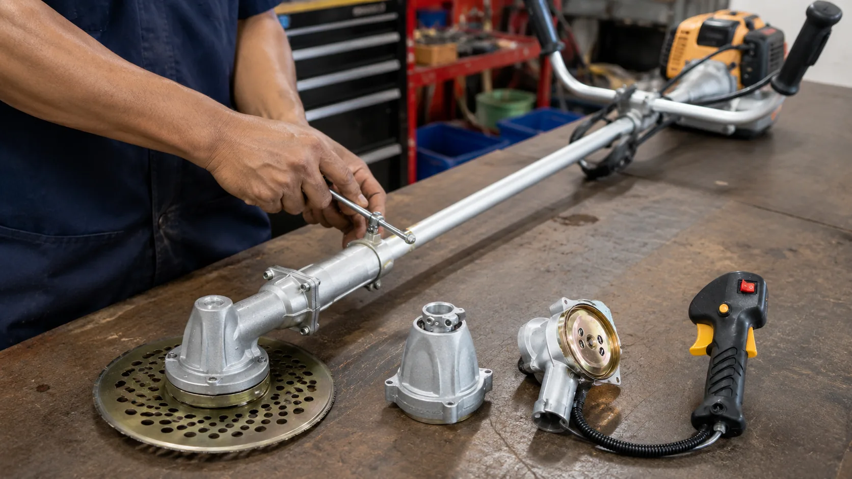
The correct repair method is to divide the machine into three sections: control, transmission and cutting head. This prevents unnecessary dismantling and helps workshops identify whether the problem is caused by insufficient engine speed, a disconnected shaft or a damaged lower gear assembly. For dealers and importers, the same diagnostic sequence also helps determine which spare parts should be stocked for local after-sales service.
| Quick answer: | A brush cutter blade that does not spin is most often caused by incomplete throttle movement, a loose or worn drive shaft connection, or a failed gear case. First confirm that the throttle control opens the carburetor fully and allows the engine to reach clutch-engagement speed. Next inspect the connector, inner shaft and spline engagement. If the shaft turns but the blade remains stationary, examine the gear case and cutting-head hardware. Importers can reduce repair errors by confirming tube diameter, shaft profile, cable connection, wiring, output thread and model compatibility before ordering replacement parts. |
01. What a Non-Spinning Brush Cutter Blade Usually Means
When the engine starts and idles normally but the blade or trimmer head remains stationary, the fault may occur anywhere along the power-transmission path. The operator presses the trigger, the throttle cable opens the carburetor, engine speed rises, the clutch engages, and the inner shaft carries rotation to the gear case. A failure at any one of these stages can produce the same visible symptom.
|
Control-side failure The trigger moves, but the throttle cable does not open the carburetor fully. The engine stays below clutch-engagement speed, making the transmission appear defective. |
Transmission-side failure The engine reaches speed and the clutch engages, but a worn spline, broken shaft, loose connector or incomplete insertion prevents rotation from reaching the lower head. |
|
Cutting-head failure Power reaches the gear case, but damaged gears, a jammed output shaft, wrapped vegetation, incorrect blade hardware or severe bearing wear prevents normal blade rotation. |
|
Repair shops should avoid replacing the most expensive component first. A new clutch or engine will not correct a disconnected drive shaft, while a new gear case will not solve a throttle cable that cannot move through its full range. Diagnosis should begin with visible and external checks before the machine is dismantled.
02. Check the Throttle Control Before Opening the Transmission
A centrifugal clutch normally begins transmitting power only after the engine rises above idle speed. If the throttle trigger cannot open the carburetor sufficiently, the blade may remain stationary even though the engine starts, sounds stable and responds slightly when the trigger is pressed.
Observe the throttle lever at the carburetor while operating the trigger with the engine switched off. The lever should move smoothly from its idle position toward full opening. Check whether the trigger sticks, the cable housing has moved out of its adjustment seat, or the inner cable is stretched, kinked or frayed. Also inspect the control handle for looseness on the operating tube.
Stop-switch wiring deserves attention because wires can become pinched during control-box installation. A damaged wire may cause intermittent ignition or restrict control movement. Do not immediately alter carburetor adjustment screws when the throttle mechanism itself is not completing its full travel.
|
Control-system replacement Brush Cutter Control Box 1102A replacement control assembly for brush cutter repair and spare-parts supply. Buyers should confirm throttle cable length, cable-end style, switch wiring, handlebar arrangement, mounting diameter and compatibility with the actual machine. |
|
03. Determine Whether the Inner Drive Shaft Is Turning
If the engine reaches normal working speed and the clutch can be heard engaging, move to the inner drive shaft. This shaft transfers rotation from the clutch drum to the lower gear case. It can fail completely, disengage at one end or continue turning with only partial spline contact.
Before inspection, stop the engine, allow hot components to cool and disconnect the spark plug cap. Remove the cutting attachment when necessary. Examine both ends of the inner shaft for rounded corners, worn splines, twisting, cracking or signs that the shaft has not entered the clutch drum or gear case deeply enough.
The outer shaft tube should also be inspected. A bent tube, displaced internal bushing or worn support bearing can prevent the inner shaft from remaining correctly aligned. Rattling, heavy vibration or intermittent blade movement may indicate that the shaft is rotating unevenly inside the tube.
- Disconnect the lower gear case and inspect the exposed shaft end.
- Rotate the shaft by hand and feel for binding, roughness or excessive free movement.
- Check engagement depth at both the clutch drum and gear case input.
- Compare the shaft profile with the receiving square or spline connection.
- Do not run the engine at high speed while major transmission parts are disconnected.
04. Loose Connectors and Incorrect Shaft Assembly
Split-shaft and multi-function brush cutters depend on accurate alignment between the upper and lower shaft sections. The outer tubes may appear fully connected while the internal square or splined drive ends remain disengaged. Tightening the locking knob does not prove that the inner shafts are transmitting power.
During assembly, slightly rotate the cutting-end shaft or attachment until the inner profiles align. The shaft section should then slide to its full insertion depth, the locating pin should enter its hole, and the clamp should hold the tube without movement. Dirt, damaged tube edges or a cracked connector housing can prevent correct insertion.
Dealers should not identify connector and shaft assemblies by engine displacement alone. Machines with similar engine sizes may use different tube diameters, shaft lengths, bearing positions, locking systems and drive profiles. A part that looks correct in a catalogue image may still be unsuitable for the customer’s machine.
Brush Cutter Connector and Shaft 1521Designed for brush cutter repair, maintenance and parts distribution. Confirm the total shaft length, tube diameter, inner shaft profile, locking method and connection with both the clutch and gear case. Procurement focus: Test installation depth and power transmission under load before approving a wholesale order. |
|
05. Gear Case Symptoms and Cutting-Head Checks
If the inner shaft rotates at the lower end but the cutting attachment does not, the gear case becomes the primary inspection point. The gear case changes the direction of rotation, supports the output shaft and carries repeated impact from blades, grass heads and contact with hard objects.
Typical gear case symptoms include grinding, clicking, rapid heat buildup, excessive side movement at the output shaft, grease leakage, difficult hand rotation or metal particles in the lubricant. A gear case may also transmit power without load but slip when the blade enters vegetation.
Before replacing it, remove grass, rope, wire and other material wrapped around the output shaft. Inspect the blade, mounting washer, blade holder, nut and guard. A bent blade, incorrect washer sequence or overtightened cutting head can create symptoms similar to internal gearbox damage.
| Observed symptom | Possible cause | Inspection point | Recommended action |
| Engine stays near idle | Trigger or throttle cable fault | Control box, cable housing and carburetor lever | Restore full throttle movement before carburetor adjustment |
| Engine accelerates but blade remains still | Disconnected or broken drive shaft | Shaft ends, insertion depth and clutch engagement | Refit or replace the confirmed worn component |
| Blade works intermittently | Rounded spline or loose connector | Connector clamp, locking pin and shaft profile | Replace worn parts and confirm full insertion |
| Blade spins in air but stops in grass | Partial engagement, worn gears or excessive cutting load | Throttle travel, clutch, shaft splines, blade and gear teeth | Correct the weakest transmission point before further use |
| Grinding or rapid gear-head heat | Gear wear, bearing damage or insufficient lubrication | Gear case input, output shaft, lubricant and bearings | Stop operation and replace or service the gear case |
|
Lower transmission replacement Brush Cutter Gear Case 1503Suitable for brush cutter and grass cutter repair stock. Verify tube diameter, input shaft profile, output thread, mounting arrangement, gear-head angle and fastening position. |
|
06. Why the Blade Spins Without Load but Stops in Grass
A blade that rotates freely in the air but stops when it contacts grass usually indicates partial power transmission or excessive resistance. The system is transferring enough torque to rotate an unloaded blade but not enough to continue cutting.
Possible causes include incomplete throttle opening, worn clutch shoes, rounded shaft splines, a slipping connector, worn gear teeth, wrapped grass, a blunt blade or a blade that is too heavy for the machine. Dense material and aggressive feeding can make a marginal transmission problem more obvious.
Observe the engine when the blade stops. If engine speed remains high, the fault is probably downstream of the engine, such as the clutch drum, shaft, connector or gear case. If engine speed drops sharply, inspect cutting load, blade sharpness, fuel delivery, throttle adjustment and clutch condition.
Dealer complaint pattern
Customers may report that the machine “works without cutting” or “loses power in grass.” Dealers should not treat both descriptions as engine faults. Testing the blade under a controlled cutting load can reveal whether the machine lacks engine speed or loses rotation within the transmission.
07. Repair Sequence and Spare-Parts Selection
A structured inspection sequence reduces wasted parts and repeat repairs. Workshops should confirm each stage of the power path before moving to the next one. New parts should be installed only after the failed section has been identified.
| 1 | Remove external resistance. Clear grass, rope and wire, then inspect the blade, holder, washers and nut. |
| 2 | Confirm throttle movement. Make sure the trigger produces full movement at the carburetor lever. |
| 3 | Listen for clutch engagement. Confirm that the engine reaches working speed before opening the shaft assembly. |
| 4 | Inspect the connector and clamps. Check full insertion, locating pin alignment and tube security. |
| 5 | Remove the inner shaft. Examine both profiles for wear, twisting and incorrect length. |
| 6 | Test the gear case by hand. Check for binding, grinding, looseness and inconsistent input-to-output movement. |
After reassembly, rotate the cutting head manually before reconnecting the spark plug. Rotation should feel consistent without grinding, severe resistance or excessive free play. When the machine is tested under power, begin at a safe speed and observe vibration, noise and blade movement before applying a cutting load.
08. Importer and Dealer Bulk-Order Checklist
Brush cutter spare parts should not be purchased only by photograph or general product name. Dimensional consistency and connection compatibility are more important than external similarity, especially when parts will be distributed to several repair shops or regional dealers.
Before Ordering
|
Before Shipment
|
For mixed-market distribution, it is often more practical to stock a controlled number of proven configurations than many visually similar parts. Importers should review which brush cutter platforms are already common in their target countries and concentrate inventory on the control boxes, shafts, connectors and gear cases that local workshops can identify easily.
Packaging should protect splined ends, electrical wires, cable adjusters, threads and machined surfaces from impact and moisture. Clear model references on the inner package and master carton reduce picking errors and make repeat orders more consistent.
Frequently Asked Questions
1. Why does my brush cutter engine run but the blade does not spin?
The engine may not be reaching clutch-engagement speed, or rotation may be lost through a disconnected shaft, worn spline, loose connector or damaged gear case. Start with throttle movement, then inspect the shaft and lower transmission.
2. Can a damaged control box stop the brush cutter blade?
Yes. If the trigger, throttle cable or cable housing does not open the carburetor fully, the engine may remain below the speed needed to engage the clutch. Inspect the control system before replacing transmission parts.
3. Why does the blade spin in the air but stop in thick grass?
This usually indicates partial power transmission, insufficient engine speed or excessive cutting resistance. Check the throttle cable, clutch, shaft splines, connector, gear teeth, blade condition and wrapped vegetation.
4. What should importers check before buying a brush cutter gear case?
Confirm the shaft-tube diameter, input profile, output thread, blade-mounting arrangement, gear-head angle and fastening position. Similar external shapes do not guarantee interchangeability.
5. How can dealers reduce after-sales complaints about non-spinning blades?
Provide a clear inspection order, stock verified compatible parts, train technicians to test the complete transmission path and avoid identifying shafts or gear cases only by engine size or visual appearance.
6. What spare parts should a brush cutter repair shop keep in stock?
Useful repair stock may include control boxes, throttle cables, inner drive shafts, shaft connectors, clutch components, gear cases, blade holders, washers, nuts and commonly used cutting attachments. Each part should be organized by actual connection dimensions.
A brush cutter blade not spinning should be treated as a complete power-transmission diagnosis. Confirm that the control box allows full acceleration, verify that the connector and drive shaft carry rotation, and check whether the gear case delivers that rotation to the blade. This inspection order helps operators and workshops repair the correct section while allowing importers to plan more reliable spare-parts inventory.
|
Spare-parts procurement support Need a compatible brush cutter transmission part?Compare the machine dimensions, shaft profile and mounting arrangement before placing a wholesale order. Begin with the component that matches the confirmed failure point. |
|