
Why Does a Brush Cutter Blade Keep Coming Loose During Use?
Find why a brush cutter blade keeps coming loose and how to inspect the nut, flange, thread direction, gearbox spindle, blade fit, and vibration safely.
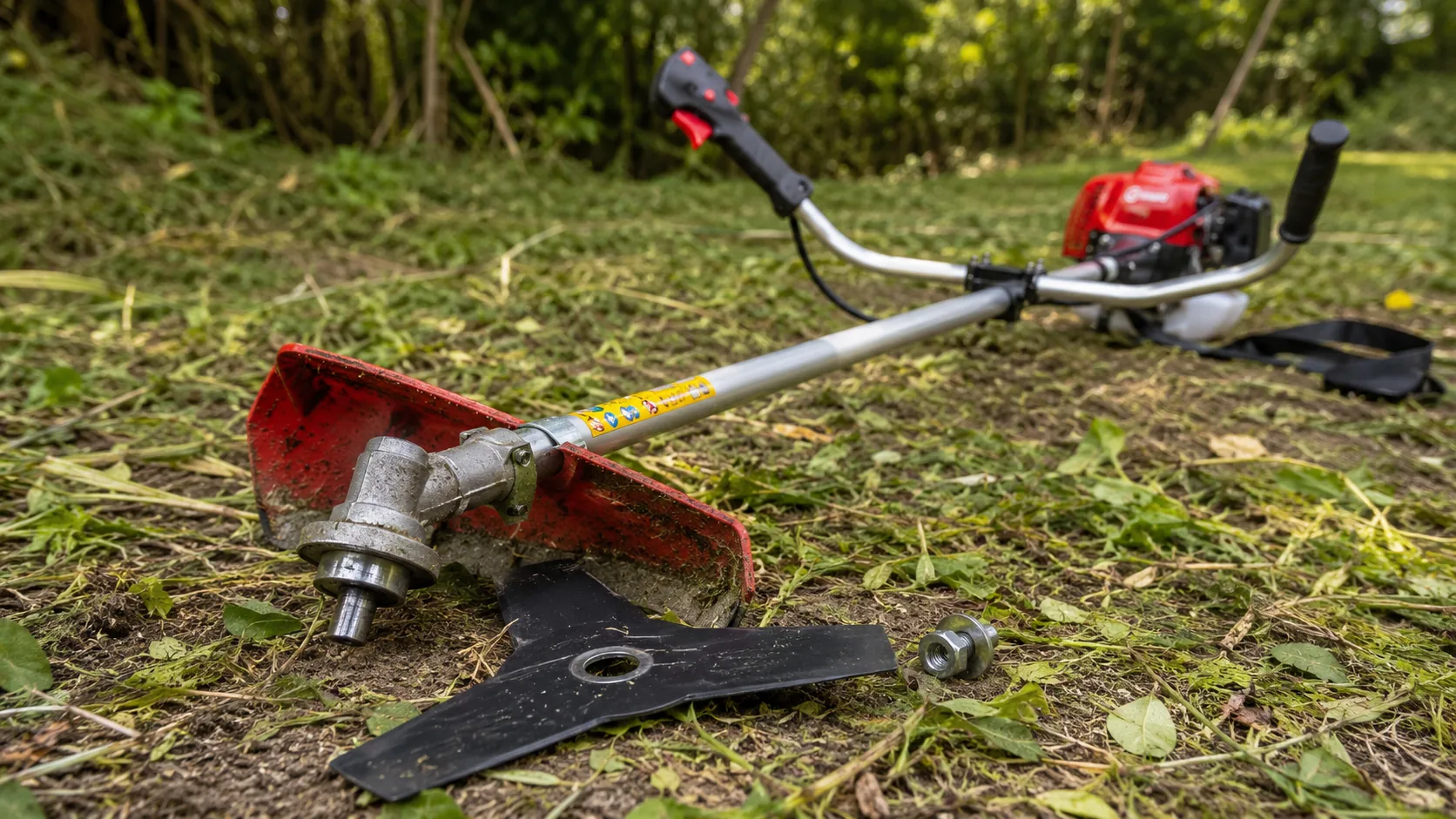
Blade Mounting Safety and Dealer Troubleshooting
Brush Cutter Blade Keeps Coming Loose: Causes, Safety Checks, and Parts Compatibility
A brush cutter blade keeps coming loose mainly because the blade-mounting sequence is incorrect, the retaining nut is tightened in the wrong direction, the blade bore does not match the locating flange, or a washer, pressure plate, protective cup, or locking component is missing. Stop the machine immediately when the blade moves on the spindle, produces new vibration, or creates a metallic knocking sound.
This is different from a blade that remains securely mounted but does not rotate. A loose blade is first a mounting and safety problem. The inspection should begin at the blade holder, nut, flange, washers, and gearbox output shaft rather than at the carburetor, clutch, or engine.
| 1 | Stop the engine and isolate the ignition. | 2 | Check thread direction and mounting order. | 3 | Confirm blade-bore and flange compatibility. |
|
Quick answer: Do not solve a repeatedly loose brush cutter blade by applying more force to the nut. Lock the gearbox shaft correctly, confirm whether the spindle uses a left-hand or right-hand thread, and arrange every mounting component in the specified order. The blade centre must sit closely around the locating flange instead of being centred only by the retaining nut. If the installation is correct but loosening continues, inspect the blade for imbalance, the spindle threads for damage, and the gearbox output shaft for abnormal play before the machine is restarted. |
|||||
Stop the Engine Before Checking the Blade Assembly
Do not continue cutting to see whether the blade nut will tighten itself. Movement between the blade, washer, flange, and spindle can wear the locating surfaces, damage the gearbox output shaft, bend the pressure plate, or allow the cutting attachment to detach.
Prepare the machine for inspection before touching any mounting component:
| 01 | Stop the engine and wait for the gearbox to cool. |
| 02 | Disconnect the spark-plug cap so the engine cannot start accidentally. |
| 03 | Drain or secure the fuel when the machine must be tilted. |
| 04 | Wear gloves and handle the metal blade by its non-cutting areas. |
| 05 | Place the brush cutter on a stable surface away from other people. |
| 06 | Check for sideways blade movement before attempting to rotate the gearbox. |
Hold the blade carefully and try moving it sideways without turning the output shaft. Any visible movement between the blade, flange, washer, cup, or spindle indicates that the assembly must be removed and inspected.
Do not rely on the blade guard to contain a detached metal blade. The guard is part of the cutting-safety system, but it does not replace correct blade clamping and compatible mounting hardware.
Confirm the Nut Thread Direction and Locking Method
A common installation error is assuming that every blade nut uses a standard right-hand thread. Many brush cutter gearboxes use a left-hand retaining thread so that normal blade rotation does not loosen the nut during operation.
| Typical Left-Hand Thread Tighten counterclockwise Loosen clockwise |
Do not treat this as a universal rule. Confirm the actual thread direction from the gearbox, spindle, original nut, manual, or supplier specification. Engine displacement and shaft-tube diameter do not determine the nut direction. |
Before applying force, clean the exposed spindle threads and inspect the original retaining nut. Insert the correct locking pin into the gearbox locking hole, then rotate the blade slowly until the output shaft is fully locked.
- Remove dirt and compacted grass from the spindle and locking hole.
- Confirm that the locking pin enters the intended gearbox hole.
- Rotate the blade until the pin engages the output shaft securely.
- Verify the nut thread direction before tightening.
- Use the correct blade tool or wrench rather than improvised extensions.
- Remove the locking pin before attempting to start the engine.
An impact wrench can damage the nut or spindle when the thread direction is wrong. It may also hide a poor mounting sequence by forcing the nut against incorrectly seated components.
Excessive tightening does not compensate for a missing flange, reversed washer, oversized blade bore, or damaged thread. The assembly must clamp correctly before final torque is applied.
Check the Mounting Sequence and Blade-Bore Fit
A typical metal-blade assembly may include an inner flange, blade, outer washer or pressure plate, protective cup, and retaining nut. The exact sequence varies with the gearbox and mounting system.
Remove the cutting attachment and lay every component on a clean surface in installation order. This is often the fastest way to identify a reversed cup, missing pressure plate, doubled washer, or incompatible part taken from another machine.
| Mounting Component | Correct Condition | Common Error | Possible Result |
| Inner flange | Sits fully against the spindle and centres the blade. | Wrong shoulder height or flange installed incorrectly. | Blade remains off-centre or cannot lie flat. |
| Blade centre bore | Fits closely around the flange locating section. | Bore is larger than the locating shoulder. | Blade shifts during acceleration and deceleration. |
| Outer washer | Contacts the blade evenly across the intended surface. | Reversed, bent, missing, or replaced with an incorrect washer. | Uneven clamping and recurring nut loosening. |
| Protective cup | Faces the specified direction and does not prevent clamping. | Installed upside down or mixed with another mounting kit. | Nut tightens against the wrong surface. |
| Retaining nut | Engages smoothly for several threads before final tightening. | Wrong pitch, wrong direction, or insufficient engagement. | Damaged threads or insecure blade mounting. |
The retaining nut provides clamping force, but it should not be the only part centring the blade. The raised locating section of the inner flange must enter the blade bore correctly. If the bore is larger than the flange shoulder, the blade can move each time engine speed changes.
An adapter ring may be required when the blade bore and flange locating diameter differ. It must fit closely, lie flat, and be intended for the mounting system. Do not use a loose, damaged, homemade, or incorrectly sized ring.
Parts from two 52cc brush cutters can appear similar while differing in bore diameter, flange shoulder height, washer thickness, spindle thread, or protective-cup shape. Similar displacement is not proof of mounting compatibility.
Inspect Threads, Blade Balance, and Vibration Sources
A retaining nut repeatedly fitted in the wrong direction may have damaged internal threads. The first spindle threads can also become flattened, crossed, or contaminated with metal particles.
Nut and Spindle Warning Signs
|
Blade Condition Warning Signs
|
The nut should rotate smoothly by hand for several threads before final tightening. If it jams immediately, do not force it using a longer wrench. A replacement nut must match the spindle diameter, thread pitch, and thread direction.
Ordering a generic “52cc brush cutter blade nut” is not enough. Engine size does not determine the gearbox output thread.
Even a correctly assembled blade can loosen when severe vibration repeatedly loads the clamping surfaces. Remove the blade and place it on a flat surface. Check whether it lies evenly and whether the centre area shows cracks, deformation, or polished movement marks.
Do not straighten a cracked or severely bent blade for continued high-speed use. Also inspect the guard, gearbox, shaft tube, handlebar, and engine mounting points because vibration felt at the handle may originate from another loose or damaged component.
Check Gearbox Output-Shaft Play and Know When to Stop
After removing the blade and all mounting hardware, hold the gearbox output shaft and check for abnormal sideways or vertical movement. Rotate it slowly and listen for roughness, clicking, grinding, or internal contact.
A small amount of movement may depend on the gearbox design. Obvious looseness, rough rotation, oil leakage, or a shaft that moves independently while the housing remains fixed requires further inspection.
| Stop-Use Condition | Reason for Inspection |
| Blade moves visibly on the spindle | Clamping or centring is not secure. |
| Metallic knocking appears during throttle changes | Blade or mounting components may be shifting. |
| New vibration begins after a blade impact | Blade, flange, spindle, gearbox, or shaft may be damaged. |
| Nut cannot engage smoothly by hand | Threads may be crossed, contaminated, or incompatible. |
| Output shaft has obvious side movement | Bearing, gear, retainer, or housing wear may be present. |
| Crack is visible near the blade centre | The blade is not suitable for further high-speed operation. |
Do not replace the complete gearbox based only on handle vibration. First remove grass, wire, and dirt from the spindle area, confirm every mounting component, and test the shaft without the blade installed.
If the output shaft itself has significant movement, fitting new washers or another blade will not remove the underlying risk. The gearbox should be serviced before another cutting attachment is installed.
Why 52cc Brush Cutter Parts Are Not Automatically Interchangeable
The TM-CG520B, TM-CG520BV, TM-CG520TB, and TM-CG520TBV are all listed as 51.7cc, two-stroke, air-cooled brush cutters with a rated output of 1.8 kW at 6,500 rpm and 28 mm shaft tubes. Their engine references, machine weights, and surrounding components are not identical.
For blade-mounting and gearbox spare parts, the model code, spindle thread, flange profile, blade bore, washer sequence, and gearbox specification are more useful than the general 52cc description.
| Model | Listed Configuration | Blade and Parts Procurement Point | Model Link | |
| TM-CG520B | 1E44F-5B engine, 28 mm shaft tube, 1,500 mm working shaft length | The shaft-tube size does not confirm the gearbox spindle thread or flange diameter. |
|
|
| TM-CG520BV | TB52 engine, 8.3 kg net weight, 9.3 kg gross weight | Blade holders, starters, carburetors, covers, and hardware should be ordered by actual model. |
|
|
| TM-CG520TB | TB52 engine, 28 mm shaft, 1:30 mixed-fuel ratio, 1,200 ml tank, 7.8 kg net and 8.8 kg gross weight | Fuel and shaft data do not establish nut thread, blade-bore, or washer compatibility. |
|
|
| TM-CG520TBV | TB52 engine, 7.5 kg net weight, 8.5 kg gross weight | A similar suffix or external appearance is not proof of gearbox or flange interchangeability. |
|
The TM-CG520B uses the 1E44F-5B engine reference, while the other compared models use the listed TB52 reference. Even where core engine data is similar, blade holders, nuts, flanges, guards, engine covers, starters, and control parts should be confirmed for the actual model.
For bulk spare-parts planning, record the gearbox code, output-shaft thread, thread direction, blade-bore size, flange locating diameter, outer-washer shape, protective-cup dimensions, shaft spline, and locking-hole position.
Operating Habits That Can Loosen or Damage the Blade
A correctly installed blade can still be damaged by repeated impact. Striking concrete edges, stones, fencing wire, hard soil, or tree stumps creates sudden reverse loading at the blade holder.
Cutting mainly with the outer blade tip can also increase impact and vibration, particularly when the blade is not intended for the material being cleared.
Avoid These Practices
|
After a Strong Blade Impact
|
After completing the repair, run a brief controlled test in a clear area. Stop the engine, disconnect the spark-plug cap, and recheck the nut and mounting surfaces before returning the brush cutter to normal work.
Importer and Dealer Blade-Mounting Checklist
Blade-related spare parts should be identified by dimensions, thread data, and model compatibility rather than broad descriptions such as “52cc blade nut” or “28 mm gearbox.”
| No. | Procurement Check | Why It Matters |
| 1 | Confirm the blade centre-bore diameter. | An oversized bore allows movement around the locating flange. |
| 2 | Record the permitted blade diameter and blade type. | Oversized or unsuitable blades can increase vibration and impact load. |
| 3 | Measure the inner-flange locating diameter and shoulder height. | The blade must sit flat and remain centred. |
| 4 | Confirm output-shaft diameter, pitch, and thread direction. | The correct nut cannot be selected by displacement alone. |
| 5 | Verify outer-washer and protective-cup dimensions. | Incorrect thickness or shape can prevent full clamping. |
| 6 | Check the shaft-tube diameter and internal drive-shaft spline. | Replacement gearboxes must match both the tube and internal drive. |
| 7 | Confirm the gearbox locking-hole position and supplied pin. | Incorrect locking methods can damage the housing or shaft. |
| 8 | List the standard blade included with each machine. | Dealers can prepare compatible replacement stock. |
| 9 | Order complete mounting kits for service inventory. | A complete kit reduces errors caused by lost or mixed washers. |
| 10 | Record approved parts by model and gearbox code. | Repeat orders remain consistent even when models look similar. |
| 11 | Confirm blade, guard, nut, and flange configuration before shipment. | The delivered cutting system must match the approved quotation. |
A complete blade-mounting kit can be useful where customers frequently lose washers or combine parts from different machines. Every component in the kit must still match the selected gearbox.
Final specifications and included accessories should be confirmed in the quotation or proforma invoice. Spare-parts compatibility must follow the selected model and confirmed order configuration.
Frequently Asked Questions
Why does my brush cutter blade nut loosen during use?
Common causes include the wrong thread direction, an incomplete mounting sequence, an oversized blade bore, damaged threads, insufficient thread engagement, blade imbalance, or gearbox shaft movement.
Does a brush cutter blade nut tighten counterclockwise?
Many brush cutter gearboxes use a left-hand thread that tightens counterclockwise, but this must be confirmed from the actual spindle, original nut, manual, or supplier specification.
Can I add another washer to stop the blade from moving?
Do not add an improvised washer to compensate for poor blade fit. An extra washer can reduce thread engagement or prevent the correct flange and pressure plate from clamping the blade evenly.
Can an unbalanced blade make the retaining nut come loose?
Yes. A bent, cracked, unevenly sharpened, or damaged blade can create repeated vibration and impact loading at the mounting surfaces. Replace an unsafe blade rather than tightening the nut more aggressively.
Are all 52cc brush cutter blade nuts and gearboxes interchangeable?
No. Models with the same displacement may use different spindle threads, flange dimensions, shaft splines, washer thicknesses, gearbox codes, or blade-bore requirements.
When should the gearbox be inspected instead of only replacing the blade hardware?
Inspect the gearbox when the output shaft has obvious side movement, rotates roughly, leaks lubricant, produces grinding noise, or continues to move abnormally after the blade and mounting parts are removed.
| Confirm the Complete Brush Cutter Mounting System
Compare the gearbox code, spindle thread, blade bore, locating flange, washers, protective cup, shaft size, and spare-parts package before selecting blades or replacement gearboxes for wholesale orders. |
|